A USB-C connector does not reveal a cable’s data ceiling. One storage benchmark does not prove that ceiling either, unless the host, specific port, protocol, enclosure or device, drive, software, power, temperature, and test conditions are known not to be the bottleneck.
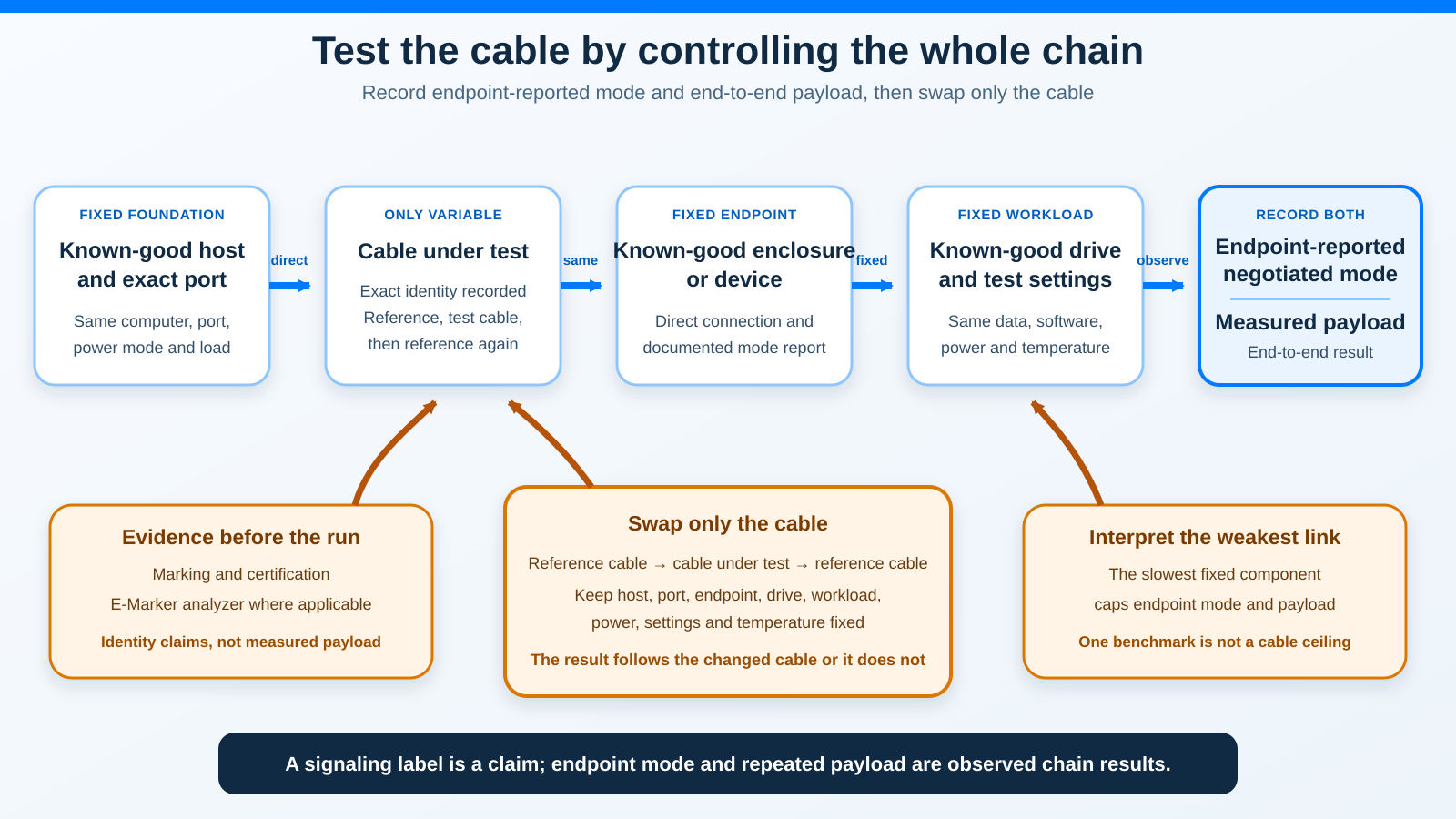
The defensible test is a controlled substitution. Start with a known-good host, port, endpoint, drive, workload, and reference cable. Record the connection mode reported by the endpoint and the repeated end-to-end payload. Then swap only the cable, repeat the same test, and restore the reference cable to confirm the baseline returns.
This gives you evidence about the cable in that exact chain. It does not turn a USB-C plug into a universal speed label, and it does not turn one file-copy number into a specification.
Five Evidence Layers, From Claim to Result
Do not collapse these five layers into one answer. Each one proves something different.
| Evidence layer | What to inspect | What it can establish | What it cannot establish |
|---|---|---|---|
| 1. Marking and exact documentation | Jacket text, connector icon, package, exact model page, manual | The performance, power, display, length, and construction claims attached to that model | What the cable actually negotiates in your setup |
| 2. Certification | Exact USB-IF or Thunderbolt product record where available | That an exact product passed a defined compliance program within its stated scope | The condition of an unknown loose cable or its live payload |
| 3. E-Marker information | A suitable analyzer, where that cable is expected to carry an E-Marker | Declared cable identity and power-related capability fields | Measured throughput, a guaranteed data class, or display support |
| 4. Negotiated connection mode | The connected endpoint’s own status surface or documented vendor utility | The mode reached by the complete connected chain | Which component caused a lower mode without substitution |
| 5. Measured payload | A fixed, repeated storage or device workload | What the complete chain delivered under recorded conditions | The cable’s universal signaling ceiling |
USB-IF separates the connector from the protocols. USB Type-C is the plug format. It is not another name for USB 3.2, USB4, USB Power Delivery, or a particular data rate. Two cables can therefore have the same ends and completely different internal wiring and electronics.
That is why the strongest answer uses more than one layer. Documentation establishes the claim. The endpoint shows the negotiated chain. A controlled workload shows payload. Substitution is what connects a change in those results to the cable.
Start With Markings and the Exact Model
Read every side of the cable, both connector shells, the original package, and the exact maker page. Record the whole label rather than copying the largest number.
A useful record includes:
- Brand and exact model or SKU
- Exact length
- Printed signaling class, if any
- USB-IF or Thunderbolt certification claim, if any
- Power class
- Display or DP Alt Mode claim
- Active or passive construction, only if documented
- Connector direction or intended device path
A printed 40Gbps label is a claim about signaling support. It is not a promise that a file copy will move at 40 gigabits per second. Protocol overhead, shared display traffic, storage media, the endpoint controller, the file system, caching, thermal behavior, and the workload all sit between a signaling label and useful payload.
An unmarked cable is not automatically USB 2.0, and a marked cable is not automatically genuine or undamaged. If you cannot connect the loose cable to a trustworthy exact model record, classify the documentation layer as unknown. Do not fill the gap from connector color, thickness, braid, or price.
If you need a documented replacement rather than a lab exercise, the USB-C cable guide keeps data, charging, video, length, and E-Marker claims separate for exact models.
What Certification Adds
A certification record is stronger than an unsupported listing title because it ties a product to a defined compliance process. Check the exact model, length or family scope, connector type, and program. A similar brand name is not enough.
Intel describes Thunderbolt certification as a rigorous process and notes that products are certified for specific operating systems. USB-IF likewise maintains certified-product records and controls its performance logos.
Certification is still not a live speed measurement. It does not tell you that the cable in your hand is the certified model, that it is undamaged, that your host supports the same mode, or that your endpoint will negotiate the advertised ceiling. Use it as identity and compliance evidence, then continue to the connection and payload layers.
For an actual Thunderbolt 5 chain, choose from exact documented models in the Thunderbolt 5 cable guide. Do not treat a generic USB4 80Gbps title as Thunderbolt certification.
What an E-Marker Read Can Prove
An E-Marker is not a tiny benchmark stored inside the cable. Where an electronic marker is applicable, it communicates declared cable identity and capability information to the connected system. Higher USB Power Delivery classes can require electronic identification, but that power evidence does not establish the data wiring.
This produces an important result that often looks contradictory: a cable can charge a demanding laptop correctly while carrying only USB 2.0 data. The power path works, while the high-speed data pairs you expected may simply not be present. The reverse inference is also unsafe. A cable without an E-Marker read is not automatically slow because not every cable class requires one.
Total Phase documents USB Type-C E-Marker verification as one function of its Advanced Cable Tester v2. That exact instrument also performs continuity, resistance, and signal-integrity work with cable-specific modules. It is a lab and production tool, not a universal consumer recommendation.
Treat the outputs separately:
- An E-Marker field is declared identity or capability evidence.
- Continuity and resistance results are electrical integrity evidence.
- Signal-integrity testing is specialized physical-layer evidence within the instrument’s documented scope.
- None of those fields is the payload negotiated by your Windows storage chain.
A power-only inline meter is a different tool. It may report voltage, current, and Power Delivery messaging, but that does not prove the cable’s data class. Keep charging-wattage work in the USB-C power meter guide and keep the data test direct.
What Windows Can Actually Tell You
Microsoft documents warnings such as USB4 device functionality might be limited, USB device functionality might be limited, and Thunderbolt device functionality might be limited. One documented cause is a cable that does not support the required USB4 capability. Microsoft advises using the cable supplied by the device or dock maker, or a certified cable, and connecting the device directly.
That warning is useful mismatch evidence. It does not contain the cable’s speed. It also does not prove the cable is the failed part, because the host port, device, firmware, adapter, or topology can produce the same broad symptom.
Do not search for a universal cable-speed number in:
- Windows Settings
- Device Manager
- WMI
- PowerShell
- A generic USB controller name
Those surfaces can help inventory a host or connected device, but Microsoft does not document one cross-vendor field that reports the cable’s data ceiling.
Instead, read the exact endpoint’s reported connection mode. An enclosure may have its own utility or documented status view. Another device may expose a negotiated mode in a vendor application. If the maker provides no supported way to see it, record not exposed rather than inventing a value.
Host capability is a separate prerequisite. Use the Windows USB-version guide to identify the computer and port, then return here to isolate the cable.
Build a Controlled Test Chain
The best practical Windows test uses a storage endpoint because it can produce a repeatable workload and many high-speed enclosures document fallback modes. The same logic works for another endpoint with a trustworthy mode report and repeatable payload test.
Use this checklist before collecting a number:
- Known-good host: Record the exact computer, firmware state, operating system, and power mode.
- One specific port: Use the same physical port for every run. Ports on one computer can have different controllers or capabilities.
- Known-good endpoint: Use one enclosure or device whose exact interface and fallback behavior are documented.
- Known-good drive or workload target: Keep the same drive, fill state, file system, data set, and destination.
- Direct connection: Remove docks, hubs, monitor passthrough, extensions, adapters, and unrelated devices from the path.
- Stable power: Connect the laptop and endpoint as their makers require. Do not change charging state between runs.
- Stable temperature: Let a hot drive, enclosure, or laptop cool. Use the same starting temperature range.
- Fixed software: Keep the same tool version, test size, run length, queue and thread settings where applicable, and destination.
- Low background activity: Pause cloud sync, updates, indexing, backups, and unrelated storage traffic.
- Known-good reference cable: Its exact model must be documented for the mode the host and endpoint share.
The known-good enclosure matters as much as the cable. A device limited to 10Gbps cannot validate a 40Gbps cable. A slow or thermally throttled drive can make two different link modes produce the same payload. The USB4 NVMe enclosure guide records exact interface and fallback claims without turning 40Gbps signaling into a fixed transfer promise.
Do not run this through a dock. A dock adds its own upstream link, internal controller, shared traffic, and supplied cable. If the dock itself is what you need to validate, first establish the cable with a direct endpoint, then use the separate USB4 hub and dock guide to check the dock’s exact topology.
Windows-First Cable Substitution Method
1. Record the fixed setup
Write down the host model, exact port, endpoint model and firmware, drive, file system, drive fill level, Windows power mode, endpoint power arrangement, software version, test size, settings, and room or starting temperature context.
This is not paperwork for its own sake. If a result changes later, the record tells you whether the cable was truly the only changed component.
2. Establish the reference baseline
Connect the known-good reference cable directly. Wait for the endpoint to appear and background setup to settle. Record any Windows notification.
Read the connection mode from the endpoint’s documented status surface. Label it endpoint-reported mode. Do not relabel it as cable speed.
Run the fixed workload multiple times after any warm-up the tool or device requires. Record every result rather than keeping only the highest, and use the same recorded run count for the reference cable and the cable under test. A range is more honest than one lucky run.
3. Swap only the cable
Stop the workload, safely disconnect the endpoint as its maker requires, and replace the reference cable with the cable under test.
Do not change the USB-C port. Do not flip to another enclosure, drive, file, benchmark profile, power adapter, or laptop mode. Do not add a dock because the test cable is too short. If another change is necessary, the comparison is no longer a one-variable cable test.
Reconnect and record:
- Exact cable identity or
unknown - Windows warning, if any
- Endpoint-reported connection mode
- Every repeated payload result
- Disconnects, retries, or device resets
- Starting and ending temperature context
4. Restore the reference
Put the known-good reference cable back and repeat the mode check and workload. The baseline should return within its normal repeated range.
This reverse swap catches background changes. If the reference is now also slow, the cable under test was not isolated. The drive may be hot, the workload may have changed, Windows may be busy, or the endpoint may be in a different state.
5. Repeat before concluding
Repeat the reference, test cable, reference sequence if the difference is close or inconsistent. A cable-specific limit is most credible when the lower endpoint mode or lower repeated payload follows the test cable and the reference baseline returns.
One-Variable Substitution Table
| Variable | Reference run | Cable-under-test run | Rule |
|---|---|---|---|
| Host and power mode | Fixed | Same | Do not reboot into a different profile between runs |
| Physical port | Fixed | Same | Do not move to a more convenient port |
| Endpoint and firmware | Fixed | Same | No second enclosure or adapter |
| Drive and data set | Fixed | Same | Preserve fill state, file system, source, and destination |
| Connection path | Direct | Direct | No hub, dock, extension, or monitor passthrough |
| Software and settings | Fixed | Same | Same version, size, queue, threads, duration, and run count |
| Temperature context | Recorded | Comparable | Cool and restart if thermal state diverges |
| Cable | Known-good reference | Cable under test | This is the only intended change |
How to Interpret the Two Results
Always interpret endpoint mode and payload together.
| What you observe | Evidence-safe conclusion | What remains unproved |
|---|---|---|
| Same mode and overlapping repeated payload | This setup did not expose a cable-specific limit | The cable’s maximum on every host, protocol, or length |
| Lower endpoint mode follows the test cable; reference mode returns | The cable is the isolated limiting change in this exact chain | The internal defect or a universal ceiling |
| Same mode, but lower repeated payload follows the test cable | Investigate integrity, retries, temperature, and the endpoint’s reporting before concluding | That the cable belongs to a lower named signaling class |
| Different endpoint mode, similar payload | The workload or drive may not be demanding enough to expose the difference | That the modes perform identically |
| Windows warning, no endpoint mode | A chain mismatch exists | Cable speed or the exact failed component |
| E-Marker identity, no connection test | Declared identity or power capability was read | Negotiated data mode or payload |
| Both cables become slow after repeated runs | A fixed component or changing condition is likely limiting the chain | A cable-specific cause |
The weakest component caps the result. A 40Gbps reference cable cannot force a 10Gbps port or endpoint to run faster. A fast endpoint cannot fix a slow drive. A benchmark cannot separate those limits by itself.
USB4 also shares its high-speed link dynamically between data and display. If a display or other traffic uses the same connection during one run, storage payload may change even though the cable did not. That is another reason to remove unrelated traffic.
Signaling Labels Are Not File-Copy Numbers
USB-IF consumer labels such as 5, 10, 20, 40, and 80 Gbps describe signaling support. They are ceilings for the applicable protocol and chain, not equivalent payload promises.
Do not publish a fixed conversion from one of those labels to megabytes per second. Useful transfer depends on encoding and protocol overhead, tunneled or shared traffic, the storage controller, media, cache, file system, workload, temperature, and software.
Thunderbolt 5 needs an extra distinction. Intel describes 80Gbps bidirectional operation. Its up-to-120Gbps Bandwidth Boost reallocates bandwidth in one direction for display-heavy use. It is not a 120Gbps symmetric storage-transfer class. A file benchmark should never be labeled 120Gbps cable speed because a Thunderbolt 5 display headline appeared on the package.
Active, Passive, and Length
Do not guess construction from length or thickness. A maker may document an active chipset for one exact long cable and passive construction for a shorter model. Those details do not transfer automatically to another brand, length, protocol, or revision.
Active electronics can also have specific compatibility boundaries. Record the exact maker’s supported protocols and directions. A cable being active does not mean it upgrades the host, preserves every older mode, or works both ways.
For testing, length and construction are part of cable identity. Compare exact cables. Do not use a one-meter result to certify a two-meter variant.
Common False Conclusions
“The plug is blue, so the cable is fast”
Connector color and shape are not a complete capability record. Use exact markings, documentation, certification, negotiated mode, and substitution.
“It charges at high power, so the data path must be fast”
Power and data are separate. An E-Marker or high power class does not prove high-speed pairs, DP Alt Mode, USB4, or Thunderbolt.
“Windows said functionality might be limited, so the cable is bad”
The warning identifies a mismatch in the chain. Test directly and change only the cable before assigning cause.
“The endpoint says 40Gbps, so my files should move at 5GB/s”
The mode is signaling evidence. Payload is lower and depends on every fixed component and the workload. Keep the two numbers separate.
“One benchmark was slow, so this is a USB 2.0 cable”
A single run can be limited by drive state, cache, temperature, software, the port, or background traffic. Record the endpoint mode and use a reference-test-reference sequence.
“The E-Marker says 240W, so the cable is fully featured”
That field concerns power identity. It does not establish data rate or video. Verify each capability independently.
“A longer cable must be active”
Only the exact maker record can establish construction. Do not infer electronics from length.
Frequently Asked Questions
Can Windows 11 tell me the speed of a USB-C cable?
Not through one universal cable-speed field. Windows can show USB, USB4, or Thunderbolt functionality-limited warnings. Read negotiated mode from the exact endpoint’s documented status surface, then isolate the cable with substitution.
Is Device Manager enough to test the cable?
No. Device Manager can help identify controllers and connected hardware, but a controller name is not the cable’s ceiling. It also cannot isolate the cable from the port, endpoint, drive, and workload.
Does an E-Marker prove 40Gbps or 80Gbps?
No. Treat E-Marker information as declared identity or capability evidence where applicable, especially for power classes. It is not measured host-to-device throughput.
Can a charging cable fall back to USB 2.0 data?
Yes. Correct charging does not prove high-speed data wiring. A high-power cable can still be documented as USB 2.0, and the data path can work at that fallback while charging normally.
What should I use as the known-good device?
Use an endpoint whose exact interface, fallback modes, firmware, power requirements, and connection-status surface are documented. Its drive or workload target must be fast enough and stable enough not to hide the mode you are testing.
How many benchmark runs should I make?
Use multiple recorded runs per cable after any consistent warm-up, then restore the reference cable. Use the same run count for the reference and test cables. Additional runs help when results overlap or temperature changes, but every setting and the run count must remain identical across the comparison.
Why did the negotiated mode change but payload barely move?
The drive, workload, cache, file system, or another fixed component may already be the bottleneck. A mode difference only creates room for more payload. It does not guarantee the workload can use it.
Does Thunderbolt 5 mean 120Gbps file transfers?
No. Intel’s 120Gbps figure is asymmetric Bandwidth Boost for display-heavy traffic. Thunderbolt 5’s normal link is described as 80Gbps bidirectional, and neither figure is a fixed storage payload.
Can I test through a dock?
Not when the goal is to isolate the cable. A dock adds another upstream cable, controller, shared traffic, firmware, and possible fallback. Establish the direct cable result first.
When is the result strong enough to blame the cable?
When a lower endpoint mode or lower repeated payload follows the cable under test, every other variable remains fixed, and the known-good reference baseline returns after the reverse swap. State the conclusion only for that exact chain.
Sources and Methodology
This guide uses direct first-party documentation retrieved on July 23, 2026. USB-IF controls the distinction between USB-C connector language, signaling classes, USB4 best-mutual-capability negotiation, shared links, and USB Power Delivery. Microsoft controls the scope of Windows USB-C limitation warnings. Intel controls Thunderbolt certification and the 80Gbps versus display-direction Bandwidth Boost distinction. Total Phase controls the exact functions and limits stated for its Advanced Cable Tester v2.
The controlled method is a synthesis of those rules and exact endpoint fallback records. It uses no personal test, invented Windows field, consumer analyzer endorsement, or signaling-to-file-copy conversion. The result is deliberately narrow: change only the cable, record endpoint-reported mode and end-to-end payload, and report what the fixed chain demonstrated.