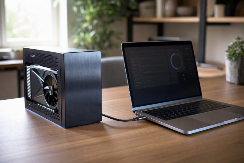
Your graphics card can support PCIe 4.0 while its active eGPU path reports PCIe 3.0. Both statements can be correct, because they describe different things. The card specification covers the card on its own, and the active reading covers the link the card ended up with through the enclosure and the host path in that setup.
Compare each layer of that path before you decide a part is faulty. A card rated for PCIe 4.0 cannot make an enclosure’s downstream PCIe port use a newer generation or more electrical lanes than the enclosure provides. A Thunderbolt or USB4 label does not state the generation and width of the PCIe link inside the enclosure either, so it cannot tell you whether that link runs at PCIe 3.0.
Map the complete eGPU path
An eGPU connection contains several links and controllers. Start at the host and follow them in order.
- The host PCIe controller connects to a Thunderbolt or USB4 host router.
- The host router places PCIe traffic into a tunnel carried over the cable.
- The enclosure’s device router and bridge receive that tunneled traffic.
- The bridge exposes a downstream PCIe port to the graphics card.
- The graphics card and that downstream port establish a PCIe generation and lane width.
The USB Implementers Forum’s USB4 System Overview shows a PCIe controller behind the host router and a PCIe switch or endpoint behind a device router, and it says PCIe traffic is tunneled over the USB4 fabric. Microsoft describes one USB4 domain as a host router plus its connected device routers. In that description the connection manager sets up the paths and manages bandwidth among the tunnels.
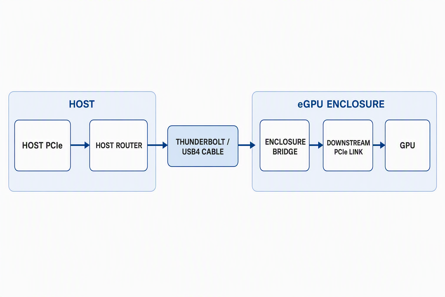
The cable carries the tunneled connection between routers. The GPU-facing PCIe link begins at the enclosure’s downstream port. Software presents the GPU inside the host’s PCIe device tree, so the host link, the tunnel, and the downstream link still need separate records.
Separate PCIe generation from lane width
PCIe generation and lane width describe different parts of a link. The generation sets the signaling rate per lane. The width is the number of lanes the link uses.
The PCI-SIG FAQ lists PCIe 3.0 at 8.0 GT/s per lane and PCIe 4.0 at 16.0 GT/s per lane. It separately describes links with widths such as x1, x2, x4, x8, and x16. A complete link description therefore needs both properties, such as PCIe 3.0 x4. A signaling rate is not application throughput and not a frame-rate result.
Physical slot length is separate from both. An x16 mechanical slot can hold an x16 card and still wire fewer electrical lanes to it. The electrical width comes from the enclosure specification or from an observed link field, never from the slot’s length.
A generation and a width are only useful together. PCIe 3.0 without a width leaves the lane count unknown, and x4 without a generation leaves the signaling rate unknown. A utility may put a supported capability and an active state in the same field, so copy the whole field instead of only the number that looks lower.
Labels from different layers are not interchangeable. Even when a host record, an enclosure record, and a card record use similar lane terms, they do not describe the same physical link unless the device tree and the source identify that link.
One exact card and enclosure record
Two official product records show how a PCIe 4.0 card and a PCIe 3.0 eGPU path can coexist.
ASUS lists the exact DUAL-RTX4070-O12G model in its Dual GeForce RTX 4070 OC Edition specifications and states that its bus standard is PCI Express 4.0. The specification establishes the card’s native capability. It says nothing about the active link once the card sits in an enclosure.
Sonnet lists one PCIe 3.0 expansion slot for the eGPU Breakaway Box 750 series, identifies that slot as x16 mechanical and x4 electrical, and names an Intel JHL6540 Thunderbolt and USB 3 controller. The record establishes a PCIe 3.0 x4 downstream ceiling for that exact enclosure and for no other model.
The two records describe different layers, so card capability and enclosure topology belong in separate evidence rows.
Classify each layer before changing hardware
Use one record for each layer. Do not let a capability from one row fill a blank in another.
| Layer | Record to keep | What the record can establish | What it cannot establish |
|---|---|---|---|
| Host controller | Exact host model, port, and controller path | The upstream controller and port used for the eGPU | The enclosure’s downstream PCIe generation or width |
| Cable and tunneled link | Exact cable and observed Thunderbolt or USB4 path | The physical path between host and enclosure routers | The graphics card’s native capability or downstream electrical width |
| Enclosure controller and bridge | Exact enclosure model, controller, and maker topology | The bridge and its documented downstream PCIe ceiling | The active state without an observation |
| Downstream PCIe link | Generation and electrical lane width reported for the GPU-facing link | The active link state for the recorded setup and condition | FPS, application throughput, or the cause of a lower state |
| Graphics card | Exact model and maker bus specification | The highest PCIe capability the card maker states | The generation or width supplied by the enclosure |
| Idle observation | Tool, field, full value, and unchanged topology | The state reported while the GPU is idle | A fault or a sustained loaded state |
| Loaded observation | Same tool and field during the same repeatable load | The state reported under that load and topology | A benchmark result or a universal performance limit |
The first row with an exact lower limit identifies the constraint. A blank row stays unknown, and an assumption about the cable, the GPU, or the enclosure does not fill it.
Freeze the setup before comparing readings
Exact identifiers are more useful here than broad categories. For the host, you need the model, the operating system build, the physical port used, and the controller path shown in the operating system’s device view. For the cable, you need the model or the markings that identify it, the length, and the maker’s supported Thunderbolt or USB4 mode. USB-C cable is not specific enough, because the connector shape does not identify the carried mode.
For the enclosure, you need the full model and part number, the controller or bridge when the maker names it, and the documented downstream PCIe generation and electrical width. For the graphics card, you need the full board model rather than the GPU family alone. An RTX 4070 name identifies a graphics processor family, while the ASUS record above applies to DUAL-RTX4070-O12G.
You also need the devices attached to the same enclosure or controller path, with a note on whether each one was idle or active. The display connections have to stay as they are. Without that setup record, two different readings could come from a changed port, cable, device load, or topology rather than from a change in the GPU-facing link.
Compare idle and loaded readings correctly
If the enclosure is detected but the graphics card is missing, work through the separate GPU-missing procedure before you read a GPU-Z Bus Interface value.
TechPowerUp GPU-Z is a link-state utility rather than a benchmark. TechPowerUp says GPU-Z includes a GPU load test to verify PCI Express lane configuration. The exact field is Bus Interface.
The topology has to be identical for both readings, which means the same host, host port, cable, enclosure, graphics card, display layout, and other connected devices.
- Open GPU-Z and record its version.
- Copy the full
Bus Interfacetext while the GPU is idle. Label the lineidle observation. - Start GPU-Z’s built-in GPU load test.
- While the test runs, copy the full
Bus Interfacetext again. Label the lineloaded observation. - Stop the test and save both strings with the topology record.
An idle value on its own does not prove that the path is limited, so the loaded value from the same setup is the one to work from. The load test puts the PCIe link in a repeatable active condition, but it does not measure game performance or application throughput.
When the loaded field reports the same generation and width that the maker documents as the enclosure’s downstream maximum, the enclosure path is the active ceiling. A PCIe 4.0 card specification does not raise that ceiling.
When the loaded field stays below the enclosure’s documented maximum, the number by itself does not name a cause. The host path, the controller tree, the firmware, the bridge record, and the topology all have to be confirmed, and until they are, the cause stays unknown. A host connection that reports reduced width belongs in the separate host-level link procedure. If the host has not yet been shown to support an external GPU path at all, the USB4 eGPU compatibility guide settles that boundary before the downstream link can be classified.
If the observation changes only when another device is active on the same upstream segment, that is a result about the shared segment rather than about the enclosure bridge. Map the shared segment before you treat the bridge as faulty.
End with a classified active-path constraint
Write the result as a short evidence record:
- Card capability: exact model and maker-stated PCIe generation.
- Host path: exact host controller, port, cable, and confirmed Thunderbolt or USB4 state.
- Enclosure path: exact controller or bridge plus documented downstream generation and electrical width.
- Observed state: GPU-Z version and full
Bus Interfacefield at idle and under the built-in load test. - Classified constraint: the first layer whose exact record sets the lower active limit, or
unknownwhen the records do not isolate it.
If an enclosure’s documented bridge or downstream PCIe topology does not meet a requirement you have already defined, compare exact controller and slot records in the Thunderbolt 5 eGPU enclosure guide. A newer enclosure label, cable, or GPU does not promise a particular link state or performance gain. The evidence covers the layer whose exact record sets the lower active limit, and it covers that layer only for the setup you recorded.